If you attach a signal generator to a speaker you can generate sounds with a specific frequency. By using two microphones and an oscilloscope you can find the wavelength of the sound waves generated. NOTE: the detected waves at each microphone can be seen as a separate wave on the oscilloscope.
Method
- Start with both microphones next to the speaker
- Slowly move one away until the two waves are aligned but exactly one wavelength apart (displayed on the oscilloscope)
- Measure the distance between the microphones to find the wavelength (λ)
- use the formula v = f x λ to find the speed (v) of the sound waves passing through the air. NOTE: the frequency is whatever you set the signal generator to.
Conclusion
Should all go well... you should find that the speed of sound in air is roughly 340 m/s
Monday, 28 March 2016
3.27 understand that the frequency range for human hearing is 20Hz - 20,000 Hz
Not much to explain here... the frequency range for human hearing is 20 Hz - 20,000 Hz.
3.26 understand that sound waves are longitudinal waves and hoy they can be rejected, refracted and diffracted
Sound waves are longitudinal waves. They can be reflected by hard flat surfaces. Materials such as carpets and curtains act as absorbing surfaces (they absorb sounds rather than reflect them). Sound waves refract as they enter a different medium (the denser the a material, the more they speed up). Sound waves can also be diffracted through gaps and around obstacles (such as a wall).
3.25 describe how digital signals can carry more information
If analogue waves are similar frequency, they can interfere with each other and lose signal quality. However, with digital signal it is much easier to tell the two waves apart, meaning more information can be transmitted along the same channel.
Furthermore, there is a process called quantisation. This is the rounding of multiple values to a smaller set. By doing this, more information can be packed into the same amount of space. As digital signals only have two values, not much information (if any) is lost due to quantisation. However, a lot can be lost when analogue is quantised.
Furthermore, there is a process called quantisation. This is the rounding of multiple values to a smaller set. By doing this, more information can be packed into the same amount of space. As digital signals only have two values, not much information (if any) is lost due to quantisation. However, a lot can be lost when analogue is quantised.
3.24 describe the advantages of using digital signals rather than analogue signals
Firstly, it is important to understand that both digital and analogue signals get weaker as they travel, so they need to be amplified along their route. Also, both signals pick up noise/interference from electrical disturbances or other signals.
However, when you amplify analogue signal, the nose it has picked up is amplified too, this worsens the quality of the signal. With digital signal, the noise is not amplified meaning the signal quality remains high.
However, when you amplify analogue signal, the nose it has picked up is amplified too, this worsens the quality of the signal. With digital signal, the noise is not amplified meaning the signal quality remains high.
3.23 understand the differences between analogue and digital signals
An analogue signal can take any value within a certiain range. The amplitude and frequency of an analogue wave can vary constantly.
A digital signal can only take two values. These values tend to be called either ON/OFF or 1/0. For example, you can send data along optical fibres as short pulses of light.
NOTE: a good way to remember which is which is that analogue is any
Credit source: CGP
A digital signal can only take two values. These values tend to be called either ON/OFF or 1/0. For example, you can send data along optical fibres as short pulses of light.
NOTE: a good way to remember which is which is that analogue is any
Credit source: CGP
3.22 know and use the relationship between critical angle and refractive index
sin c = 1 / n
NOTE: n means refractive index
NOTE: n means refractive index
3.21 explain the meaning of critical angle c
When light travels through different materials, it is refracted. If light ray is shone through a medium at certain angle (known as the 'critical angle' or 'angle c') the light will be refracted at 90º. If the light ray is shone at a greater angle than angle c, the light will be reflected back into the medium it is in (this is known as total internal reflection).
This diagram shows what happens when a ray of light is shone at angle c...

NOTE: the critical angle is different for different mediums
Saturday, 26 March 2016
3.20 describe the role of total internal reflection in transmitting information along optical fibres and in prisms
Optical fibres (which are made of glass or plastic), consist of a central core surrounded by cladding that has a lower refractive index (of the glass or plastic). The central core is so narrow that light signals passing through the core always hit the cladding boundaries at angles higher than C (critical angle). This means that the light is always totally internally reflected. This total internal reflection will only not occur if the optical fibre is bent too sharply.
Optical fibres are used to transmit information. Total internal reflection is very useful in optical fibres as no information is lost (it is all reflected back into the core), also, light travels very fast.
Optical fibres are used to transmit information. Total internal reflection is very useful in optical fibres as no information is lost (it is all reflected back into the core), also, light travels very fast.
Friday, 25 March 2016
3.19 describe an experiment to determine the refractive index of glass, using a glass block
Method
- Draw around a rectangular glass block.
- At an angle, shine a ray of light (from a light box) through it. Trace the incident and emergent rays.
- Take away the glass block, draw the refracted ray (by joining up the incident and emergent rays).
- At the point where the ray entered the block, draw the normal at 90º to the edge of where the block was.
- Use a protractor to measure the angle if incidence (i) and the angle of refraction (r). NOTE: remember to measure from the normal line
- Calculate the refractive index (n) using the equation n = sin i / sin r
Presuming all is well, your diagram should look something like this...
3.18 know and use the relationship between refractive index, angle if incidence and angle of refraction
the refractive index of a transparent material tells you how fast light travels in that material. The slower the light travels, the higher the refractive index
n = sin i / sin r
NOTE: n symbolises refractive index, i symbolises angle of incidence, r symbolises angle of refraction
n = sin i / sin r
NOTE: n symbolises refractive index, i symbolises angle of incidence, r symbolises angle of refraction
Wednesday, 23 March 2016
3.15 use the law of reflection (the angle if incidence equals the angle of reflection)
The law of reflection applies to every single reflected ray...
Angle of incidence = angle of reflection
NOTE: these two angles are always measured between the normal (dotted line) and the ray itself.
Angle of incidence = angle of reflection
NOTE: these two angles are always measured between the normal (dotted line) and the ray itself.
3.13 understand the detrimental effects of excessive exposure of the human body to electromagnetic waves and describe simple protective measures against them
Microwaves: internal heating of body tissue
Problem: Microwaves have a similar frequency to the vibrations of many molecules and so they can increase these vibrations, resulting in internal heating. In this way, microwaves can internally heat human body tissue.
Protective measure: microwaves ovens need to have shielding to prevent microwaves escaping and reaching the person using it (or anyone else around)
Infrared: skin burns
Problem: he infrared range of frequencies can make the surface molecules of substances vibrate, like microwaves, this results in a heating effect. However, infrared has a higher frequency, so it carries more energy than microwave radiation. IF human flesh is exposed to too much IR radiation, skin burns can result.
Protective measure: you can protect yourself using insulating materials to reduce the amount of IR reaching your skin.
Ultraviolet: damage to surface cells and blindness
Problem: UV radiation can damage surface cells and cause blindness. It is 'ionising', this means it carries enough energy to knock electrons off atoms. This can case cell mutations (which can lead to cancer)
Protective measure: Wear suncream with UV filters if out in the sun and stay out of strong sunlight
Gamma rays: cancer, mutation
Problem: Gamma rays have very high frequency and are ionising, they carry more energy than UV rays and therefore can penetrate the body much further. They can cause cell mutation or destruction, which leads to tissue damage and cancer.
Protective measure: Radioactive sources of gamma rays should be kept in lad-lined boxes when not in use. Should someone need to be exposed to gamma radiation(e.g. in chemotherapy) the exposure time should be kept as short as possible.
Source of most information: CGP
3.12 explain some of the uses of electromagnetic radiations
Radio waves: broadcasting and communications
Radio waves are used mainly for communication. This is because they have long wavelengths (over 10m) which s very useful. Long-wave radio (wavelengths of 1-10km) can be transmitted from London (for example) to half way around the globe. This is because long wavelengths are the best at diffracting, so they can bend around the earth and also arounds opticals such as hills and tunnels.
Radio waves used for broadcasting have mush shorter wavelengths (10cm-10m), these do not bend well so you have to be in direct sight of the transmitter, the is why T.V ariels are positioned on top of houses.
NOTE: as well as long-wave radio signals, short-wave and medium-wave also exist. Short wave radio signals (10m-100m) can also be received long distance from the transmitter because they are reflected from the ionosphere (an electrically charged layer in the Earth's upper atmosphere). Medium-wave signals can also reflect from the ionosphere (but this depends on the atmospheric conditions and the time of day)
Microwaves; cooking and satellite transmissions
Microwaves have wavelengths of around 1cm-10cm, they are used for satellite communication and cooking.
Satellite communication needs to use wavelengths of microwaves which can easily pass through the Earths atmosphere without bing absorbed. For a satellite T.V (for example) to work, the signal from a transmitter is transmitted into space where it is picked up by the satellite receiver did that is orbiting thousands of kilometre above Earth. The satellite transmits the signal back to Earth in a different direction where it is received by a satellite dish on the ground. Mobile phone calls also travel as microwaves from your phone to the nearest transmitter.
Microwaves in ovens have a different wavelength to those used in communication. These microwaves penetrate a few centimetres into the food before being absorbed by water molecules in the food.
Infrared: heaters and night vision equipment
Infrared radiation is also known as heat radiation. Infrared radiation is given out anything and everything, and the hotter the object, the more IR radiation is given out. Examples of infrared radiation in everyday phenomena include electrical heaters and grills. Electrical heaters radiate infrared to keep us warm and grills radio infrared to cook food.
Furthermore, the infrared radiation that objects give out can be picked up/detected during nighttime (or pitch black) by night-vision equipment. the equipment turns the IR that has been radiated into an electrical signal which is displayed on a screen as a picture, meaning things that otherwise would go amiss (e.g. a criminal hiding) to be seen.
Visible light: optical fibres and photography
Visible light can also be used in communication using optical fibres which carry data over long distances as pulses of light.
Optical fibres work by bouncing waves off the sides of a very narrow core. The beam of light enters the fibre at a certain angle as one end and is reflected again and again (known as 'total internal reflection' until it emerges at the other end...

Optical fibres are often used for telephone and broadband internet cables. They are also used in hospitals to see inside the body without having to operate.
Visible light is also used for photography. Cameras use a lens to focus visible light onto a light-sensitive film or electronic sensor (the lens aperture controls how much light enters the camera). The shutter speed determine how long the film or sensor is exposed to the light. by varying the aperture and shutter speed a photographer can capture as much/little light as they want
Ultraviolet: fluorescent lamps
Florescent colours look so bright because it is where ultraviolet radiation (UV) is absorbed and visible light is emitted.
This basically means that fluorescent lights use UV radiation to emit visible light. They are safe to use as nearly all the UV radiation is absorbed by a phosphor coating on the inside of the glass (which emits visible light instead). This is more energy-efficient than filament light bulbs.
X-rays: observing the internal structure of objects and materials and medical applications
To produce an X-ray image, X-ray radiation is directed through your body (or an object you wish to X-ray) onto a detector plate (which starts off white). X-rays can easily pass through mediums such as flesh but not through dense mediums such as bone. The brighter bits (e.g. bones) are where fewer X-rays get through - this is a negative image.
Gamma rays: sterilising food and medical equipment
Medical equipment is sterilised by gamma rays as they kill ass the microbes. This is more effective than boiling equipment as this could potentially cause damage.
Food can be sterilised the same was as medical equipment (by killing the microbes). Is is perfectly safe to eat afterwards, as in like its not radioactive etc.
Radio waves are used mainly for communication. This is because they have long wavelengths (over 10m) which s very useful. Long-wave radio (wavelengths of 1-10km) can be transmitted from London (for example) to half way around the globe. This is because long wavelengths are the best at diffracting, so they can bend around the earth and also arounds opticals such as hills and tunnels.
Radio waves used for broadcasting have mush shorter wavelengths (10cm-10m), these do not bend well so you have to be in direct sight of the transmitter, the is why T.V ariels are positioned on top of houses.
NOTE: as well as long-wave radio signals, short-wave and medium-wave also exist. Short wave radio signals (10m-100m) can also be received long distance from the transmitter because they are reflected from the ionosphere (an electrically charged layer in the Earth's upper atmosphere). Medium-wave signals can also reflect from the ionosphere (but this depends on the atmospheric conditions and the time of day)
Microwaves; cooking and satellite transmissions
Microwaves have wavelengths of around 1cm-10cm, they are used for satellite communication and cooking.
Satellite communication needs to use wavelengths of microwaves which can easily pass through the Earths atmosphere without bing absorbed. For a satellite T.V (for example) to work, the signal from a transmitter is transmitted into space where it is picked up by the satellite receiver did that is orbiting thousands of kilometre above Earth. The satellite transmits the signal back to Earth in a different direction where it is received by a satellite dish on the ground. Mobile phone calls also travel as microwaves from your phone to the nearest transmitter.
Microwaves in ovens have a different wavelength to those used in communication. These microwaves penetrate a few centimetres into the food before being absorbed by water molecules in the food.
Infrared: heaters and night vision equipment
Infrared radiation is also known as heat radiation. Infrared radiation is given out anything and everything, and the hotter the object, the more IR radiation is given out. Examples of infrared radiation in everyday phenomena include electrical heaters and grills. Electrical heaters radiate infrared to keep us warm and grills radio infrared to cook food.
Furthermore, the infrared radiation that objects give out can be picked up/detected during nighttime (or pitch black) by night-vision equipment. the equipment turns the IR that has been radiated into an electrical signal which is displayed on a screen as a picture, meaning things that otherwise would go amiss (e.g. a criminal hiding) to be seen.
Visible light: optical fibres and photography
Visible light can also be used in communication using optical fibres which carry data over long distances as pulses of light.
Optical fibres work by bouncing waves off the sides of a very narrow core. The beam of light enters the fibre at a certain angle as one end and is reflected again and again (known as 'total internal reflection' until it emerges at the other end...
Optical fibres are often used for telephone and broadband internet cables. They are also used in hospitals to see inside the body without having to operate.
Visible light is also used for photography. Cameras use a lens to focus visible light onto a light-sensitive film or electronic sensor (the lens aperture controls how much light enters the camera). The shutter speed determine how long the film or sensor is exposed to the light. by varying the aperture and shutter speed a photographer can capture as much/little light as they want
Ultraviolet: fluorescent lamps
Florescent colours look so bright because it is where ultraviolet radiation (UV) is absorbed and visible light is emitted.
This basically means that fluorescent lights use UV radiation to emit visible light. They are safe to use as nearly all the UV radiation is absorbed by a phosphor coating on the inside of the glass (which emits visible light instead). This is more energy-efficient than filament light bulbs.
X-rays: observing the internal structure of objects and materials and medical applications
To produce an X-ray image, X-ray radiation is directed through your body (or an object you wish to X-ray) onto a detector plate (which starts off white). X-rays can easily pass through mediums such as flesh but not through dense mediums such as bone. The brighter bits (e.g. bones) are where fewer X-rays get through - this is a negative image.
Gamma rays: sterilising food and medical equipment
Medical equipment is sterilised by gamma rays as they kill ass the microbes. This is more effective than boiling equipment as this could potentially cause damage.
Food can be sterilised the same was as medical equipment (by killing the microbes). Is is perfectly safe to eat afterwards, as in like its not radioactive etc.
3.11 identify the order of the electromagnetic spectrum in terms of decreasing wavelength and increasing frequency, including the colours of the visible spectrum
The electromagnetic spectrum is grouped into seven types of waves that have different wavelengths. The order is...
Radio waves (longest wavelength)
Microwaves
Infrared waves
Visible Light
Ultraviolet
X-Rays
Gamma rays (shortest wavelength)
NOTE: I use this song to remember the order... https://www.youtube.com/watch?v=ZPwG4zZNOu4
The colours of the visible light spectrum also depend on wavelength. The order is
Red (longest wavelength)
Orange
Yellow
Green
Blue
Indigo
Violet
NOTE: a good way to remember this is Richard Of York Gave Battle In Vain (sorry, may only work for english students as we learn this is history when were like 5 but if you can, try and remember it. Otherwise, if you have any other acronyms that are easy to remember, please comment them!)
3.10 understand that light is part of a continuous electromagnetic spectrum which includes radio, microwave, infrared, visible, ultraviolet, x-ray and gamma ray radiations and that all these waves travel at the same speed in free space
The electromagnetic spectrum is a range of different frequency waves. The spectrum is split into radio, micro, infrared, light, ultra violet, x-ray and gamma. All of these waves travel at the same speed in a vacuum, they are also all transverse waves.
3.9 understand that waves can be diffracted through gaps, and that the extent of diffraction depends on the wavelength and the physical dimension of the gap
The size of the gap relative to the size of the wavelength is also important...

3.8 understand that waves can be diffracted when they pass an edge
When a wave meets an obstacle, it could be reflected, refracted or diffracted.
If they are diffracted this just means that the edges of the waves 'bend' to get through gaps, this causes the waves to spread out and allows for waves to travel around corners.
The amount of diffraction depends on the size of the gap relative and the wavelength of the wave, the narrower the gap or the longer the wavelength, the more the wave spreads out
Here's what happens...
3.6 use the relationship between frequency and time period
frequency = 1 / time period
f = 1 / T
(yes, its a capital T)
f = 1 / T
(yes, its a capital T)
3.5 know and use the relationship between the speed, frequency and wavelength of a wave
wave speed = frequency x wavelength
In symbols: v = f x λ
In symbols: v = f x λ
3.4 understand that waves transfer energy without transferring matter
Waves carry/transfer every in the direction they're traveling in. For example, microwaves in an oven make things warm up. This is because they transfer heat energy to the food that is in the oven. However, microwaves do not transfer any particles or matter or anything to the food, just energy.
3.3 define amplitude, frequency, wavelength and period of a wave
Amplitude - this is the height of the wave (from rest to crest)
Frequency - the frequency is how many complete waves there are per second, it is measures in Hz (1 Hz is 1 wave per second)
Wavelength (λ)- this is the distance from one crest (or trough) to the other crest (or trough). It is represented in equations as lambda (λ)
Period (of a wave) - this is the time it takes for one complete wave to pass. It is measures in seconds (s)
3.2 understand the difference between longitudinal and transverse waves and describe experiments to show longitudinal and transverse waves in, for example, ropes, springs and water
Transverse (the uppy-downy ones)
Most waves are transverse (light waves and all waves of the electromagnet spectrum). In transverse waves the vibrations are at 90º to the direction energy is transferred by the wave
Longitudinal (the other ones)
Longitudinal waves include sound (and ultrasound) waves and shock waves (e.s. seismic waves). In longitudinal waves the vibrations are along the same direction as the energy transferred by the waves
If you have any spare time, it would be a great idea to watch this video, it is a little long but very helpful!...
https://youtu.be/jAXx0018QCc
Sunday, 20 March 2016
3.1 use the following units: degree, hertz, metre, metre/second, second
degree, measure of angle, °
hertz, measure of frequency, Hz
metre, measure of distance, m
metre/second, measure of speed, m/s
second, measure of time, s
hertz, measure of frequency, Hz
metre, measure of distance, m
metre/second, measure of speed, m/s
second, measure of time, s
Saturday, 19 March 2016
2.25 explain some uses of electrostatic charges, e.g in photocopiers and inkjet printers
Photocopiers
In photocopiers, there is an image plate which is positively charged, an image of what you are photocopying is then projected onto it. The charge leaks away from the white/light parts of what your copying as they make light fall on the plate. The dark/black parts of what your copying remain charged and attract negatively charged black power, which is transferred onto positively charged paper. Next, the paper is heated to stick the powder down.
Inkjet printers
In an inkjet printer, tiny droplets of ink are forced out of a fine nozzle, this makes them electrically charged. The droplets are then deflected as they pass between two metal plates. A voltage is applied to the plates, one is negative and the other is positive. The droplets are attracted the the plate of the opposite charge and repelled from the plate with the same charge - the size and direction of the voltage across each plate constantly changes so that each droplet is deflected to hit a different place on the paper.
2.23 explain electrostatic phenomena in terms of the movement of electrons
This is quite confusing and may need a few reads to fully understand...
The movement of electrons is responsible for all phenomena relating to current electricity. However, electrostatic phenomenon, such as electrostatic induction , is the transfer of electrons from one body to another.
For example, polythene and cloth. When they are rubbed together, the rod will gain electrons and become positively charged and the cloth will lose electrons and become negatively charged.
2.24 explain the potential dangers of electrostatic charges, e.g when fuelling aircraft and tankers
Problem
As fuel flows out of a filler pipe (the pipe thing that you put in your car, etc), static electricity can build up. This can easily lead to a spark, which can cause a fire in dusty/fumy places.
Solution
Make the nozzle of the filler pipe out of metal so that the charge is conducted away instead of building up (as the building up of electrostatic charge will cause a spark).
It is also good to have earthing straps between a feeling tank and the fuel pipe, to earth the charge, avoiding a build up of the charge.
Friday, 18 March 2016
2.22 understand that there are forces of attraction between unlike charges and forces of repulsion between like charged
- Two materials with opposite electrostatic charges are attracted to each other
- Two materials with the same electrostatic charge will repel
NOTE: like magnets, these forces get weaker the further apart the two materials are
- Two materials with the same electrostatic charge will repel
NOTE: like magnets, these forces get weaker the further apart the two materials are
2.21 explain that positive and negative electrostatic charged are produced on materials by the loss and gain of electrons
When two insulating materials are rubbed together, they become electrostatic ally charged. This is because the electrons are transferred from one material onto the other. For example, when polythene rod (this has a negative charge) is rubbed against a cloth, (this has a positive charge), all the electrons move from the cloth to the polythene rod. This leaves the polythene rod negatively charged (as it has gained electrons) and the cloth positively charges (as it has lost electrons).
A way of remembering this is with the anagram, NIGPIL (yes i made it up, if you remember it tough, it does work!). It stands for...
Negative Is Gain - as the material that gains electrons becomes negatively charged
Positive Is Loss - as the material that loses electrons becomes posotively charged
NOTE: Which material transfers which electrons will depend on the two materials involved - it will not always be the cloth losing electrons/the rod gaining electrons.
2.20 describe experiments to investigate how insulating materials can be charged by friction
When two insulating materials are rubbed together, electrons will pass from one insulator onto the other insulator.
Rub a cloth on a polythene rod. Electrons will move from the duster to the rod. The rod will become negatively charged and the cloth will become equal positively charged. To check, hold the rod and the cloth near a pile of small bits of paper, the bits of paper will be attracted to the rod/cloth as they are electrically charged.
Alternatively, you could use an acetate rod and cloth, it involves the same process and, therefore, the same outcome will occur. The only difference is that the acetate rod will be positively charged and the cloth will become negatively charged.
2.19 identify common materials which are electrical conductors or insulators, including metals and plastics
Materials that are electrical conductors conduct charge easily (basically, a current can flow through them), they are usually metals (although not always). Examples include copper and silver
Electrical insulators do not conduct charge well at all (basically, a current can't flow). Examples include plastic and rubber.
Electrical insulators do not conduct charge well at all (basically, a current can't flow). Examples include plastic and rubber.
2.18 understand that: voltage is the energy transferred per unit charge passed, the volt is a joule per coulomb
Voltage is the energy transferred per unit charge passed, it is measures in volts. One volt is one joule per coulomb.
2.17 know that electric current in solid metallic conductors is a flow of negatively charged electrons
Electric current is the rate of flow of electrical charge (in amperes, A) around a circuit, in solid metal conductors (for example, a copper wire), charge is carried by negatively charged electrons.
Thursday, 17 March 2016
2.16 know and use the relationship between charge, current and time.
Charge = current x time
Q = I x t
Example...
A battery charger passes a current of 2.5A over a cell for a period of 4 hours. How much charge does the charger transfer to the cell altogether?
Firstly, cover 4 hours into seconds... 4 x 60 x 60 = 14,400 seconds.
now substitute into the equation...
Charge = 2.5 x 14,400 = 36,000 C (36 kC)
(charge is measured in coulombs, C)
Random fact that we need to know but doesn't really fit anywhere: the bigger the current the bigger the charge
2.15 understand that current is the rate of flow of charge
Charge cane positive or negative, and when it flows it is known as current. Therefore, current is the rate of flow of charge around a circuit, it will only flow through a component if there is a voltage across that component. The unit is Amps (or amperes), A.
2.14 know and use the relationship between voltage, resistance and current.
Voltage = current x resistance
V = I x R
Example..
a 4Ω resistor in a circuit has a voltage of 6V across it. What is the current through the resistor?
Firstly, rearrange the equation because we are finding I, the substitute what we know into it...
I = V/R
Therefore, Current = V/R = 6/4 = 1.5 A
Current = 1.5 A
V = I x R
Example..
a 4Ω resistor in a circuit has a voltage of 6V across it. What is the current through the resistor?
Firstly, rearrange the equation because we are finding I, the substitute what we know into it...
I = V/R
Therefore, Current = V/R = 6/4 = 1.5 A
Current = 1.5 A
2.13 know that lamps and LEDs can be used to indicate the presence of a current in a circuit
If there is a light in a circuit, it will be lit if there is a current in the circuit and not lit if there is no current. The same applies to LEDs (Light Emitting Diodes).
2.12 describe the qualitative variation of resistance of LDRs with illumination and of thermistors with temperature
LDRs and Thermistors are components that can change their resistance (aka, it is not always the same).
An LDR (Light Dependant Resistor) changes its resistant depending on how much light falls on it. For example, in bright light the resistance is low and in darkness the resistance is at its highest.
A thermistor is a temperature-dependant resistor (its resistance changes depending on the temperature). For example, in hot conditions the resistance is low and in cooler conditions the resistance is high.
2.11 describe the qualitative effect of changing resistance on the current in a circuit
Increasing resistance (by adding components such as lamps or diodes) will decrease the current, decreasing resistance (removing components) will increase current.
2.10 describe how current varies with voltage in wires, resistors, metal filament lamps and diodes, and how this can be investigated experimentally
Resistors (e.g lamps and diodes) lessen the flow of current, whilst voltage increases the current. This can be investigated using an ammeter (measures current) and a voltmeter (measures voltage).
Set up a circuit like this (known as the 'standard test circuit')...
Interchange the component with different resistors for example a lamp or diode, and record the recordings on the ammeter.
Also, increase/decrease the voltage and note the change on the ammeter.
Compare and contrast results. Overall, increasing the voltage should increase the number on the ammeter (current) whilst resistors (the components) will lower the current.
2.9 understand that the current in a series circuit depends on the applied voltage and the number and nature of other components
In a circuit, the voltage is the driving force.
Any component added into the circuit (for example, a lamp) will increase the amount of resistance in the circuit, this will decrease the current.
The voltage is trying to push the current around the circuit and the resistance is trying to slow it down, therefore, the relative sizes of the voltage and resistance decide how big the current will be.
If you increase the voltage - more current will flow
If you increase the resistance - less current will flow (alternatively, if you want the same amount of current to fly when the resistance is increased, you could increase the voltage).
Monday, 14 March 2016
6.20 know and use the relationship between input power and output power
VPIP =VSIS
(for 100% efficiency)
(for 100% efficiency)
6.19 know and use the relationship between input (primary) and output (secondary) voltages and the turns ratio for a transformerinput (primary) voltage = primary turns output (secondary) voltage secondary turns
primary voltage / secondary voltage = turns on primary / turns on secondary
Vp/Vs = Np/Ns
NOTE: 'N' stands for number of coils
6.18 explain the use of step-up and step-down transformers in the large- scale generation and transmission of electrical energy
Transformers are used in the National Grid. This is because the wires are long there is more resistance, so a high current will cause a lot of heat which is dangerous and looses a lot of energy (it is not energy efficient). When electricity leaves a power plant/generator, a step up transformer is used, this increased the voltage but decreases the current. When electricity reaches nearby the areas it is to be used, for example factories and edge of towns, it is stepped down. Once the wires reach a home or business it is stepped down once more (to 230v) to make it useful in appliances that we use.
6.17 describe the structure of a transformer, and understand that a transformer changes the size of an alternating voltage by having different numbers of turns on the input and output sides
Transformers are used to change the current and voltage of electricity.
How they work...
A wire carrying a current is wrapped round one side of the transformer, another wire is wrapped round the other. There will be the same amount of power on both sides, but one will have a higher voltage and lower current the other a lower voltage and a higher current.
The transformer is made of iron, this is because it is a soft metal and can be turned on and off as a magnet (it is a magnetically soft material): the current from the first wire induces a magnetic field in the transformer, this then induces a current in the second wire.
More coils causes more higher voltage (and lower current). So if the second side has more turns of wire wrapped round the transformer it will step the voltage up (step up transformer.) If the second side has less turns, the voltage will be stepped down and current increased (step down transformer).
If your having trouble getting to grips with this (it is very hard!), the animation at the bottom of this page may help... http://www.bbc.co.uk/schools/gcsebitesize/science/edexcel/generation_transmission_electricity/transmitting_electricityrev2.shtml
6.16 describe the generation of electricity by the rotation of a magnet within a coil of wire and of a coil of wire within a magnetic field and describe the factors which affect the size of the induced voltage
If you rotate a magnet in a coil of wire, a current will be induced. Also, if you rotate coil of wire in a magnetic field a current will be induced.
Factors that increase the electricity induced...
- Strength of magnetic field
- Number of coils in wire
- Speed of rotations
Factors that increase the electricity induced...
- Strength of magnetic field
- Number of coils in wire
- Speed of rotations
6.15 understand that a voltage is induced in a conductor or a coil when it moves through a magnetic field or when a magnetic field changes through it and describe the factors which affect the size of the induced voltage
- If you more a wire back and forth in a magnetic field or through a coil (solenoid), a voltage will be induced.
- Increasing the magnetic field strength, quickening the speed your moving the wire or increasing the number of coils, will all increase the voltage.
- Increasing the magnetic field strength, quickening the speed your moving the wire or increasing the number of coils, will all increase the voltage.
6.14 describe how the force on a current-carrying conductor in a magnetic field increases with the strength of the field and with the current.
Lets say, for example, you have a wire in a magnetic field. If you increase the current there will be more force on the wire; if you increase the strength of the magnetic field there will be fore force on the wire, meaning more force on the conductor.
6.13 use the left hand rule to predict the direction of the resulting force when a wire carries a current perpendicular to a magnetic field

The magnetic field finger is pointing south.
The current finger is pointing negative.
6.12 understand that a force is exerted on a current-carrying wire in a magnetic field, and how this effect is applied in simple d.c. electric motors and loudspeakers
If a current through a piece of wire is held at right angles to a magnetic field, the wire will move (as a force is created)
When a current flowing through a wire is put through a magnet, the magnetic field lines overlap.
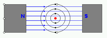

in some places, the direction of the fields are the same, and the magnetic field is stronger. in other places, the direction of the fields are in opposite directions, so the magnetic field is weaker.
the wire is pushed from the strong part of the field to the weak part (the magnetic field lines don’t like being squished together)
electric motors
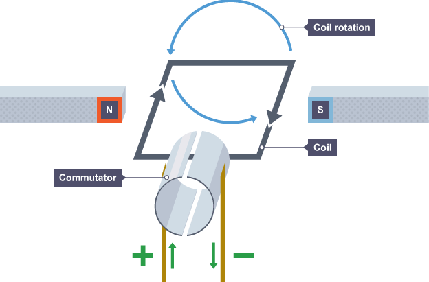
the magnets on the two sides of the coil are at different directions. One side feels the force pushing it downwards, whilst the other is being pushed upwards, so the coil rotates.
the direction current on each side of the coil is switched when the coil is vertical by the commutator, so the forces acting on each side is switched and the rotation direction is maintained
to increase rate of motor turns:
- increase the number of turns or loops of wire (to make a coil)
- increase the strength of the magnetic field
- increase current flowing through the loop of wire
- increase the number of turns or loops of wire (to make a coil)
- increase the strength of the magnetic field
- increase current flowing through the loop of wire
cr:phychembi.tumblr.com
6.11 understand that there is a force on a charged particle when it moves in a magnetic field as long as its motion is not parallel to the field
If a charged particle moves into a magnetic field, it experiences a force pulling it in the direction of the field.
When a charged particle, that is parallel to the magnetic field line, entres the magnetic fiend line, it will not experience a force. This is because the charged particle is already going in the direction of the magnetic field.
When a charged particle, that is parallel to the magnetic field line, entres the magnetic fiend line, it will not experience a force. This is because the charged particle is already going in the direction of the magnetic field.
6.10 sketch and recognise magnetic field patterns for a straight wire, a flat circular coil and a solenoid when each is carrying a current
Straight wire
A magnetic field around a straight wire is a series of circles around the wire

Flat circular coil
A magnetic field around a flat circular coil is pretty much the same as a single wire, only there are two

Solenoid
A magnetic field around a solenoid is similar to a magnetic field around a bar magnet.

A magnetic field around a straight wire is a series of circles around the wire
A magnetic field around a flat circular coil is pretty much the same as a single wire, only there are two
A magnetic field around a solenoid is similar to a magnetic field around a bar magnet.
NOTE: Ignore the B=thing but do take note of where the current goes in and out represented by "I"
6.9 describe the construction of electromagnets
An electromagnet is a solenoid with an iron core inserted into it. If a current flows in the coil, a magnetic field is generated. Therefore, to make an electromagnet all you need to do is wrap a piece of wire around a magnetically soft material. When a current is induced in a wire, the magnetically soft material becomes magnetised. The coil is knows as a solenoid.
6.8 understand that an electric current in a conductor produces a magnetic field round it
If you run an electric current through any conductor of electricity (for example, a wire), a magnetic field will be produced around the conductor. However, this field is quite weak ( it is also in a circular shape).

If it helps, use the 'right hand rule' to find which direction the magnetic field runs.
If it helps, use the 'right hand rule' to find which direction the magnetic field runs.
6.7 describe how to use two permanent magnets to produce a uniform magnetic field pattern.
If you put two bar magnets very near each other (bar magnets are the ones that are not horseshoe, they look like bars), with their north and south poles facing the magnetic field lines will be parallel. If the magnetic field lines are parallel to each other we have a field of constant strength – this is a uniform field.


6.6 describe experiments to investigate the magnetic field pattern for a permanent bar magnet and that between two bar magnets
Iron filings
Plotting compass
Plotting compass
(NOTE: this really is not complicated at all, i just couldn't work out an easy way of describing it)
6.5 understand that magnetism is induced in some materials when they are placed in a magnetic field
Some materials that are not magnetic can become magnetic if they are in a magnetic field. In this situation the material acts as a magnet - but only whilst in the magnetic field. This is induced magnetism and only occurs with magnetically soft materials.
6.4 understand the term ‘magnetic field line’
Magnetic field lines are a representation of the shape and direction of a magnetic field.
NOTE: the gaps in the lines to not represent gaps in the magnetic field. Also, a magnetic field is actually 3D, the lines just give an idea of the strength of a field etc.
NOTE: the gaps in the lines to not represent gaps in the magnetic field. Also, a magnetic field is actually 3D, the lines just give an idea of the strength of a field etc.
6.3 describe the properties of magnetically hard and soft materials
Hard
Substances that can be permanently magnetised are known as magnetically hard. They retain their magnetic properties for a long period of time (sometimes permanently) and they are hard to de-magnetise. These are often alloys of iron, nickel and cobalt.
Soft
Substances that can only be temporarily magnetised are known as magnetically soft. They lose all its magnetic properties very quickly (almost as soon as they leave a magnetic field). Alloys with less iron, nickel or cobalt will be magnetically soft and have a weaker magnetic field.
Kinda random note that doesn't really fit anywhere but we need to know: Alloys of iron are called ferrous and those without iron are called non-ferrous.
6.2 understand that magnets repel and attract other magnets and attract magnetic substances
- Opposite poles of magnetism attract (North attracts to South, South attracts to North)
- The same poles repel (North repels North, South repels South)
- Magnetic substances, such as paperclips, can also be attracted by magnets
- The same poles repel (North repels North, South repels South)
- Magnetic substances, such as paperclips, can also be attracted by magnets
6.1 use the following units: ampere (A), volt (V), watt (W).
- Ampere (A), measure of electric current
- Volt (V), measure of voltage
- Watt (W), measure of power
- Volt (V), measure of voltage
- Watt (W), measure of power
Saturday, 12 March 2016
2.8 explain why a series or parallel circuit is more appropriate for particular applications, including domestic lighting
Series
In a series circuit, all components are connected on one line. This means that the voltage is shared between every component equally making it useful for supplying low power things, for example fairy lights. However, as the components are connected along one line, they can not be individually turned on, you can turn on all or none. Also, if one component breaks, the rest of the circuit will not work.
In a series circuit, all components are connected on one line. This means that the voltage is shared between every component equally making it useful for supplying low power things, for example fairy lights. However, as the components are connected along one line, they can not be individually turned on, you can turn on all or none. Also, if one component breaks, the rest of the circuit will not work.

The circuit diagram above shows a circuit with two lamps connected in series. If one lamp breaks, the other lamp will not light.
Parallel
In a parallel circuit different components are connected separately to the supply. This means that, unlike in a series circuit, if one component breaks the other components can continue being powered as the whole circuit can still function. This makes it useful for powering objects that require a high power things as the voltage is equal throughout the circuit (therefore, each component receives the full voltage).

The circuit diagram above shows a circuit with two lamps connected in parallel. If one lamp breaks, the other lamp will still light.
2.7 understand the difference between mains electricity being alternating current (a.c.) and direct current (d.c.) being supplied by a cell or battery.
There are two different types of electricity: alternating current and direct current.
Mains electricity is alternating current (AC). Alternating current changes from one direction to another rapidly. Direct current is electricity supplied by cells and batteries, it flows in ones direction only.
Mains electricity is alternating current (AC). Alternating current changes from one direction to another rapidly. Direct current is electricity supplied by cells and batteries, it flows in ones direction only.
2.6 use the relationship between energy transferred, current, voltage and time
- energy transferred = current × voltage × time
E=I×V×t
(as power = IxV, E=IxVxt is the same as E=Pxt)
2.5 know and use the relationship between power, current and voltage and apply the relationship to the selection of appropriate fuses
-
The power of an electrical appliance can be calculated from the current that flows through it and the potential difference (voltage) across it.You can work out power using this equation:P = I × VP is the power (in watts, W)I is the current (in amperes/amps, A)V is the potential differences (in volts, V)Example
- What is the power of a 5 A 1.5 V lamp?
- Power = 5 × 1.5 = 7.5 W
Working out the best fuse to use
The equation P = I × V can be rearranged to find the current if the power and potential difference (voltage)are known:I = P ÷ VExampleWhat current flows through a 1.15 kW electric fire at a potential difference of 230 V? (Remember that 1.15 kW is 1,150 W)Current = 1150 ÷ 230 = 5AFuses come in standard ratings of 3 A, 5 A or 13 A.The best fuse to use in this example would be the 13A fuse. The 3A and 5A fuses would blow even when the fire was working normally.
2.4 understand that a current in a resistor results in the electrical transfer of energy and an increase in temperature, and how this can be used in a variety of domestic contexts
Resistors work by slowing down the movement of electrons and the kinetic energy that was moving them is converted into thermal (heat) energy . This can be used to heat objects, for example, in hairdryers and heaters.
2.3 understand the uses of insulation, double insulation, earthing, fuses and circuit breakers in a range of domestic appliances
Insulation
All insulation is is covering a live wire (a wire that is conducting electricity) with a material that is not an electrical conductor. This means the wire is safe to touch as the current is contained within the wiring as it can't pass through the layer of insulation.
Earthing
Double insulation
Some appliances, for example vacuum cleaners and electric drills, do not have an earth wire. This is because they have plastic casings, or they have been designed so that the live wire cannot touch the casing. As a result, the casing cannot give an electric shock, even if the wires inside becomes loose and touched the casing.
Fuses
Circuit Breakers
Circuit breakers contain an electromagnet that activates if the current goes above a certain limit (different limits for different appliances). Should the current go above the limit of an appliance, the electromagnet pulls an iron switch towards it, this opens the switch, consequently breaking the circuit.
All insulation is is covering a live wire (a wire that is conducting electricity) with a material that is not an electrical conductor. This means the wire is safe to touch as the current is contained within the wiring as it can't pass through the layer of insulation.
Earthing
Many electrical appliances, for example cookers, washing machines and fridges have metal cases. The earth wire creates a safe route for the current to flow through if the live wire touches the metal casing (otherwise the current would flow through the case and it is likely you would get an electric shock).
However, the earth wire is connected to the metal casing so that the current goes through the earth wire instead of causing an electric shock. A strong current surges through the earth wire because it has a very low resistance. This breaks the fuse and disconnects the appliance.
Double insulation
Some appliances, for example vacuum cleaners and electric drills, do not have an earth wire. This is because they have plastic casings, or they have been designed so that the live wire cannot touch the casing. As a result, the casing cannot give an electric shock, even if the wires inside becomes loose and touched the casing.
Fuses
If a fault in the circuit causes too much current to flow, the fuse breaks the circuit. The fuse contains a piece of wire which melts easily. If the current going through the fuse is too great, the wire heats up until it melts and breaks the circuit.
Fuses in plugs are made in standard ratings. The most common are 3 A, 5 A and 13 A. The fuse should be rated at a slightly higher current than the device needs. Foe example, if the device works at 3 A, use a 5 A fuse, if the device works at 10 A, use a 13 A fuse.
Circuit Breakers
Circuit breakers contain an electromagnet that activates if the current goes above a certain limit (different limits for different appliances). Should the current go above the limit of an appliance, the electromagnet pulls an iron switch towards it, this opens the switch, consequently breaking the circuit.
Residual current circuit breakers (RCCBs) protect some circuits. They detect a difference in the current between the live and neutral wires. RCCBs work much faster than fuses do. (For exams, you do not need to know how they work, just what they do)
2.2 understand and identify the hazards of electricity including frayed cables, long cables, damaged plugs, water around sockets, and pushing metal objects into sockets
Frayed cables
When a cable is frayed, the insulation around the wire(s) has worn down, this exposes live wires which would potentially conduct electricity, if you come into contact with a live wire you could get electrocuted.
Long cables
Long cables are easily tangled which increases resistance, they also pose a trip hazard. Also, as they are longer, they have a higher risk of overheating (you do not need to know why, you just need to know that they do)
Damaged plugs
If a plug is damaged, some of the safety features may be broken. This is hazardous.
Water around sockets
Water is a very good conductor of electricity. If energy from the circuit gets into the water it can flow through the water creating an electrocution risk
Pushing metal into sockets
Metal, like water, is also a conductor of electricity Therefore, is energy from the current touches metal the energy will travel through the metal, anyone touching/holding the metal with the current running through it may be electrocuted.
Friday, 11 March 2016
2.1 use the following units:
- Ampere, (A), measure of electrical current
- Coulomb, (C), measure of electrical charge
- Joule, (J), measure of energy
- Ohm, (Ω), measure of resistance (and conductance - not needed for IGCSE though)
- Second , (s), measure of time
- Volt, (V), measure of voltage
- Watt, (W), measure of power
- Coulomb, (C), measure of electrical charge
- Joule, (J), measure of energy
- Ohm, (Ω), measure of resistance (and conductance - not needed for IGCSE though)
- Second , (s), measure of time
- Volt, (V), measure of voltage
- Watt, (W), measure of power
Tuesday, 8 March 2016
1.36 understand that: the universe is a large collection of billions of galaxies a galaxy is a large collection of billions of stars our solar system is in the Milky Way galaxy
-
- The universe contains many galaxies
- Each galaxy contains many stars
- Each star has its own solar system
- Our solar system is in a galaxy called the Milky Way
1.35 use the relationship between orbital speed, orbital radius and time period
-
orbital speed = 2 x π x orbital radius time period /time period
v = 2 x π x r / t
1.34 describe the differences in the orbits of comets, moons and planets
Planets and moons both orbit in circle paths
Comets orbit in ovals known as ellipticals
Comets orbit in ovals known as ellipticals
1.33 explain that gravitational force: causes moons to orbit planets causes the planets to orbit the sun causes artificial satellites to orbit the Earth causes comets to orbit the sun
if an object entres the field of another objects gravitational force, it will travel around the object in an orbit.
This causes...
- planets to orbit the sun
- artificial satellites to orbit earth
- comets to orbit the sun
- moons to orbit planets
This causes...
- planets to orbit the sun
- artificial satellites to orbit earth
- comets to orbit the sun
- moons to orbit planets
1.32 understand gravitational field strength, g, and recall that it is different on other planets and the moon from that on the Earth
Gravitational field strength (g) is how strongly something pulls an object towards it.
On Earth it is 9.8 (rounded to 10)
Earth has a higher gravitational field strength than the moon. This is because they have different masses, the Earth has more mass than the moon, therefore the Earth has a bigger gravitational field strength than the moon - the bigger the planet/object (as comets and stars can have g too) the bigger the gravitational field strength.
1.31 describe elastic behaviour as the ability of a material to recover its original shape after the forces causing deformation have been removed
Elastic behaviour is the idea that when you stretch an elastically object it will return to its original shape after the forces stretching it stop stretching it.
For example...
When you stretch an elastic band and then let it go it pings back to regain its original shape and size.
For example...
When you stretch an elastic band and then let it go it pings back to regain its original shape and size.
1.30 understand that the initial linear region of a force-extension graph is associated with Hooke’s law
Hooke's law stated that the force needed to extend (or compress) a spring is proportional to the distance it is extended (or compressed).
a force extension graph shows how much a material stretches in proportion to how much force is applied.
The initial linear region is the straight diagonal line showing a linear correlation between force and extension, basically meaning that they increase at the same rate (this is Hooke's law).
At some point, the graph will curve, this is when the spring reaches its elastic potential, the extension and force are no longer proportional.
Subscribe to:
Posts (Atom)