Showing posts with label section 3. Show all posts

Sunday, 22 May 2016

3.16 construct ray diagrams to illustrate the formation of a virtual image in a plane mirror

When light rays bounce off an object onto a mirror, a virtual image is formed. A ray diagram shows how this image is produced (in a plane mirror)

Method

- firstly, draw a line from the top of the object to the reflective surface (in this example it is a lake, although it could be a mirror/shiney surface etc)
- reflect the incidence engle in the reflective surface and draw the reflective
 (into a human eye_
- now continue the ray from the eye through the reflective surface until it is in line with the real image.
- repeat with a line from the bottom of the real image.
- the lines will now show where the top and bottom of the virtual image are, just fill in by drawing in the image.


(sorry that was a little confusing)

3.14 understand what light waves are transverse waves which can be reflected, refracted and diffracted

Light waves are transfers which means the energy travels perpendicular to matter.

The reflection of light is what lets us see things. Light bounces off objects into our eyes. the light ray will hit a reflective surface (e.g a mirror) and will bounce back at the same angle on the other side of the normal line.

If a wave refracts all it is doing is bending/changing direction. this occurs when a wave enters a medium of different density. When they return to the/a medium of the original density, they will travel in the same direction as started.


Diffraction is just when the waves 'disperse', sort of. If the waves hit a barrier with a small opening, they will bunch up and spread out after the opening, on the other side.

3.7 use the above relationships in different contexts including sound waves and electromagnetic waves

okay so the 'above relationships' are wave speed = frequency x wavelength and frequency = 1 / time period

We just need to be able to substitute what we are given in questions into the equation. Here are some examples...

1- Find the speed of a wave of wavelength 12m and frequency 4Hz

To answer this, we use the equation wave speed = frequency x wavelength, so, 12 x 4 = 48. Therefore, the wave speed of this wave is 48 seconds. (NOTE: fyi, this is a really unrealistic wave speed, this is just an example of how to sub in the equation!)

2- A wave has a period of 0.35 seconds. Find the frequency of this wave.

For this question, we need to use the equation frequency = 1 / time period. We know the period is 0.35, so all we need to do is 1 / 0.35 = 2.857 which rounds to 2.86. so the frequency of this wave is 2.86Hz

Friday, 1 April 2016

3.32 relate the loudness of a sound to the amplitude of vibration

If there is a bigger amplitude, the sound will be louder, if there is a smaller amplitude, the sound will be quieter.

3.31 relate the pitch of a sound to the frequency of vibration of the source

The frequency is the complete number of vibrations per second. If the wave has a high frequency, the pitch is high (e.g a squeak), comparatively, if you have a low frequency (not very many oscillations per second), the pitch will be low (e.g a bear).

3.30 describe an experiment using an oscilloscope to determine the frequency of a sound wave

Method

- Plug a microphone into an oscilloscope
- Make a noise into the microphone (e.g. have someone sing a single note)
- Count the amount of oscillations per second (an oscillation is one complete wave, basically the wavelength)\

This is the frequency (as frequency is wavelength/time)

3.29 understand how an oscilloscope and microphone can be used to display a sound wave

A sound wave receiver (microphone, for example) picks up sound waves that are trade;;ing through the air. In order to display these waves (which is useful for measuring properties etc), you can plug the receiver into an oscilloscope (a decide which displays he microphone signal as a trace on a screen). The receiver will convert the sound waves to electrical signals. The appearance of the wave (basically what it looks like) can tell you whether the sound is loud or quiet, low or high pitched etc. You can also take measurements to calculate frequency etc (this is done by adjusting the display of the oscilloscope).

Reading the oscilloscope - the greater the amplitude of the wave, the more energy it carried. In sound, this means the greater the amplitude the louder the sound.

Monday, 28 March 2016

3.28 describe an experiment to measure the speed of sound in air

If you attach a signal generator to a speaker you can generate sounds with a specific frequency. By using two microphones and an oscilloscope you can find the wavelength of the sound waves generated. NOTE: the detected waves at each microphone can be seen as a separate wave on the oscilloscope.

Method

- Start with both microphones next to the speaker
- Slowly move one away until the two waves are aligned but exactly one wavelength apart (displayed on the oscilloscope)
- Measure the distance between the microphones to find the wavelength (λ)
- use the formula v = f x λ to find the speed (v) of the sound waves passing through the air. NOTE: the frequency is whatever you set the signal generator to.

Conclusion
Should all go well... you should find that the speed of sound in air is roughly 340 m/s

3.27 understand that the frequency range for human hearing is 20Hz - 20,000 Hz

Not much to explain here... the frequency range for human hearing is 20 Hz - 20,000 Hz.

3.26 understand that sound waves are longitudinal waves and hoy they can be rejected, refracted and diffracted

Sound waves are longitudinal waves. They can be reflected by hard flat surfaces. Materials such as carpets and curtains act as absorbing surfaces (they absorb sounds rather than reflect them). Sound waves refract as they enter a different medium (the denser the a material, the more they speed up). Sound waves can also be diffracted through gaps and around obstacles (such as a wall).

3.25 describe how digital signals can carry more information

If analogue waves are similar frequency, they can interfere with each other and lose signal quality. However, with digital signal it is much easier to tell the two waves apart, meaning more information can be transmitted along the same channel.

Furthermore, there is a process called quantisation. This is the rounding of multiple values to a smaller set. By doing this, more information can be packed into the same amount of space. As digital signals only have two values, not much information (if any) is lost due to quantisation. However, a lot can be lost when analogue is quantised.

3.24 describe the advantages of using digital signals rather than analogue signals

Firstly, it is important to understand that both digital and analogue signals get weaker as they travel, so they need to be amplified along their route. Also, both signals pick up noise/interference from electrical disturbances or other signals. 

However, when you amplify analogue signal, the nose it has picked up is amplified too, this worsens the quality of the signal. With digital signal, the noise is not amplified meaning the signal quality remains high.

3.23 understand the differences between analogue and digital signals

An analogue signal can take any value within a certiain range. The amplitude and frequency of an analogue wave can vary constantly.

A digital signal can only take two values. These values tend to be called either ON/OFF or 1/0. For example, you can send data along optical fibres as short pulses of light.

NOTE: a good way to remember which is which is that analogue is any

Credit source: CGP

3.22 know and use the relationship between critical angle and refractive index

sin c = 1 / n

NOTE: n means refractive index

3.21 explain the meaning of critical angle c

When light travels through different materials, it is refracted. If light ray is shone through a medium at certain angle (known as the 'critical angle' or 'angle c') the light will be refracted at 90º. If the light ray is shone at a greater angle than angle c, the light will be reflected back into the medium it is in (this is known as total internal reflection).

This diagram shows what happens when a ray of light is shone at angle c...

NOTE: the critical angle is different for different mediums

Saturday, 26 March 2016

3.20 describe the role of total internal reflection in transmitting information along optical fibres and in prisms

Optical fibres (which are made of glass or plastic), consist of a central core surrounded by cladding that has a lower refractive index (of the glass or plastic). The central core is so narrow that light signals passing through the core always hit the cladding boundaries at angles higher than C (critical angle). This means that the light is always totally internally reflected. This total internal reflection will only not occur if the optical fibre is bent too sharply.

Optical fibres are used to transmit information. Total internal reflection is very useful in optical fibres as no information is lost (it is all reflected back into the core), also, light travels very fast.

Friday, 25 March 2016

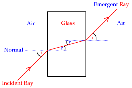
3.19 describe an experiment to determine the refractive index of glass, using a glass block

Method
- Draw around a rectangular glass block.
- At an angle, shine a ray of light (from a light box) through it. Trace the incident and emergent rays.
- Take away the glass block, draw the refracted ray (by joining up the incident and emergent rays).
- At the point where the ray entered the block, draw the normal at 90º to the edge of where the block was.
- Use a protractor to measure the angle if incidence (i) and the angle of refraction (r). NOTE: remember to measure from the normal line
- Calculate the refractive index (n) using the equation n = sin i / sin r

Presuming all is well, your diagram should look something like this...

3.18 know and use the relationship between refractive index, angle if incidence and angle of refraction

the refractive index of a transparent material tells you how fast light travels in that material. The slower the light travels, the higher the refractive index

n = sin i / sin r


NOTE: n symbolises refractive index, i symbolises angle of incidence, r symbolises angle of refraction

Wednesday, 23 March 2016

3.15 use the law of reflection (the angle if incidence equals the angle of reflection)

The law of reflection applies to every single reflected ray...

Angle of incidence = angle of reflection

NOTE: these two angles are always measured between the normal (dotted line) and the ray itself.

3.13 understand the detrimental effects of excessive exposure of the human body to electromagnetic waves and describe simple protective measures against them

Microwaves: internal heating of body tissue
Problem: Microwaves have a similar frequency to the vibrations of many molecules and so they can increase these vibrations, resulting in internal heating. In this way, microwaves can internally heat human body tissue.

Protective measure: microwaves ovens need to have shielding to prevent microwaves escaping and reaching the person using it (or anyone else around)


Infrared: skin burns
Problem: he infrared range of frequencies can make the surface molecules of substances vibrate, like microwaves, this results in a heating effect. However, infrared has a higher frequency, so it carries more energy than microwave radiation. IF human flesh is exposed to too much IR radiation, skin burns can result.

Protective measure: you can protect yourself using insulating materials to reduce the amount of IR reaching your skin.


Ultraviolet: damage to surface cells and blindness
Problem: UV radiation can damage surface cells and cause blindness. It is 'ionising', this means it carries enough energy to knock electrons off atoms. This can case cell mutations (which can lead to cancer)

Protective measure: Wear suncream with UV filters if out in the sun and stay out of strong sunlight


Gamma rays: cancer, mutation
Problem: Gamma rays have very high frequency and are ionising, they carry more energy than UV rays and therefore can penetrate the body much further. They can cause cell mutation or destruction, which leads to tissue damage and cancer.

Protective measure: Radioactive sources of gamma rays should be kept in lad-lined boxes when not in use. Should someone need to be exposed to gamma radiation(e.g. in chemotherapy) the exposure time should be kept as short as possible.

Source of most information: CGP